Axial Force Equation on an Enclosed Impeller
April 19th, 2021
The axial and radial loads placed on the impeller have an important effect on the reliable operation of a pump. Since the impeller is rigidly connected to the rotor bearings if these loads become too large the excessive bearing heat and shortened life may be experienced.
Typically the pump is designed so that these loads are minimized, but some amount of thrust is inevitable and can be magnified by unfavorable operating conditions.
In this posting, we are discussing the calculation of axial thrust.
- Thrust on the Front Shroud Ff (In the direction of the motor)
- Thrust on the Back Shroud Fb (In the direction of the inlet)
- Thrust Due to Suction Pressure Fs (In the direction of the motor)
- Thrust Due to Momentum Change of Fluid
- Seal Spring Force
- Gravity
To understand and calculate the axial force, it is helpful to divide the force into a number of components. The total axial force results from the sum of each component. Each of the components listed below, with the exception of the 5th & 6th bullets, is caused by the fluid forces on the impeller.
To simplify the discussion, we assume that the pump has an enclosed impeller. For a semi-open impeller, the calculations are slightly different because of the absence of a front shroud.
Thrust on the front shroud Ff (In the direction of the motor)
The discharge of the impeller naturally experiences some of the highest pressures in the pump casing. This pressure is translated towards the front and back of the impeller shrouds. At first approximation, one might estimate that the pressure at the front of the impeller is equal to the discharge pressure of the pump.
However, the observed pressure at the front shroud will be below the discharge pressure of the pump, due to the rotation of the fluid in the space between the impeller in the casing wall. This rotation of the fluid will create a pressure gradient that acts to lessen the pressure closer to the axis of rotation. The greater the spin of the fluid in the space, the lower pressure.
Several authors have derived formulas that take as an assumption that the fluid in the space rotates at half the speed of the impeller. In the formula below a coefficient C, in the range between 0.5 and 0.75 is given as a starting point.
![]()
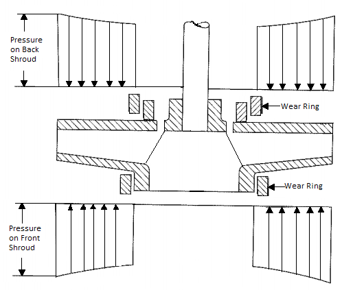
Thrust on the back shroud Fb (In the direction of the inlet)
This is calculated in a manner similar to the forces on the front shroud. A complicating factor would be the presence of a rear wear ring or back pump-out vanes. Back pump-out vanes would increase the swirl between the impeller and casing, resulting in a reduction in static pressure. Back wear rings when used with balance holes, will reduce the static pressure behind the associated part of the impeller.
![]()
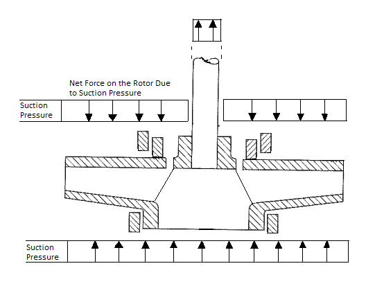
Thrust Due to Suction Pressure Fs (In the direction of the motor)
With a slight of hand, we calculate the net effect of suction pressure as the area of the pump shaft multiplied by the suction pressure. In reality, the suction pressure increases pressure on all inner surfaces of the pump.
However, other than the area of the shaft, the suction pressure acts on the front and back of any given surface, canceling itself out. Therefore, to determine the net effect of suction pressure we only consider the area of the shaft that extends through the casing or pressure boundary, where an offsetting suction pressure is absent.
![]()
Thrust due to momentum change of Fluid
In a typical end suction pump, the fluid enters the impeller axially then the force of the impeller changes the direction of fluid flow to the radial direction. For most radial flow centrifugal pumps, this amounts to a near 90-degree change in direction.
The component of fluid flow in the axial direction brought to zero and it requires a force to make this happen. This force is directly applied by the impeller. Since force is equal to the rate of change of momentum, we simply need to calculate the momentum coming into the pump per unit time along the axial direction.
![]()
As a sanity check, we note that the units of the above formula are mass x length / time2 which is the same as the units of force, giving us extra comfort.
Seal spring force
This one often is forgotten. One end of the seal will sit against the casing while the other sits against a ring that is affixed to the shaft. Therefore it is true that the seal spring will apply axial force. Typically the spring will push the rotor away from the motor. The magnitude of the spring force is typically not large.
Gravity
In the case of vertical pumps, we also have gravity pulling the rotor downwards. In most cases this force is small, however, for long sump pumps and vertical turbine pumps, this force can be significant.
Conclusion
For the vast majority of applications, our designs ensure that axial loads are kept at a low level. However, certain high suction pressure applications may result in a significant reduction in bearing life. Precise calculation of the above forces is important for the design and application of pumps, particularly in challenging environments involving high suction pressure, high flow, or when dealing with heavy rotors for vertical pumps.